| Home > LEO Computers > Lyons Electronic Office (LEO) Archive > CMLEO/PB - Peter Bird Collection > CMLEO/PB/CS LEO Compu ... ny Secretary's Papers > 62309 Programme for ... Lenaerts, 8 Aug 1949 |
62309 Programme for Mr Lenaerts, 8 Aug 1949
| Home > LEO Computers > Lyons Electronic Office (LEO) Archive > CMLEO/PB - Peter Bird Collection > CMLEO/PB/CS LEO Compu ... ny Secretary's Papers > 62309 Programme for ... Lenaerts, 8 Aug 1949 |
|
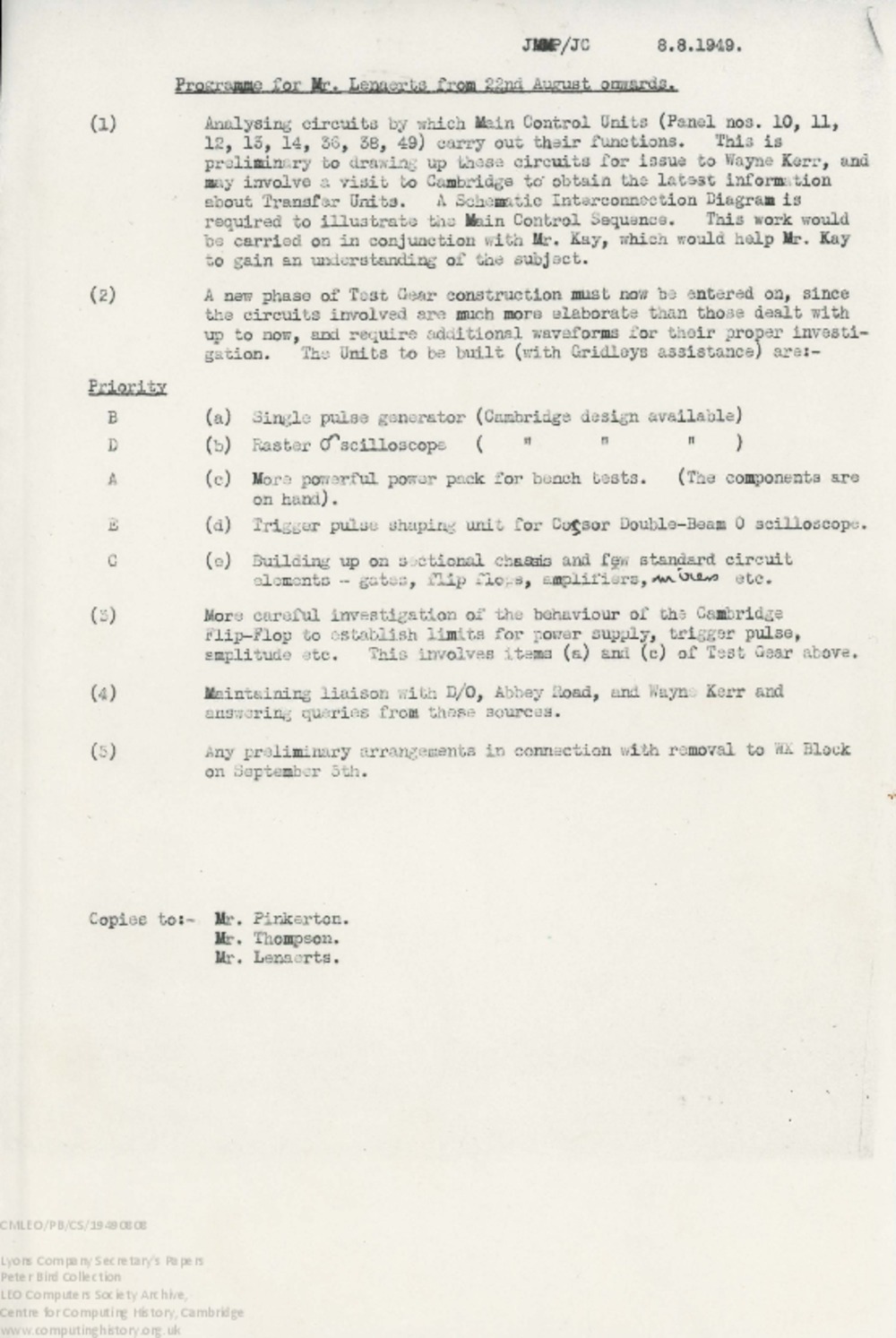
TS internal Lyons memo from John Pinkerton: Programme for Mr Lenaerts from 22nd August onwards, 8 Aug 1949. Research Comments: Once EDSAC had successfully run its first program and Lyons had given the go-ahead for the development of LEO, Ernest Lenaerts returned to Cadby Hall to start work on LEO, having been at Cambridge to help with the development of EDSAC. Lyons had set up a workshop in the lodge of St Mary's College, part of the Cadby Hall site, for development work to begin and initially Lenaerts was based there. This document lists the various tasks Lenaerts would work on, which included circuit development work for LEO's main control units (based on EDSCAC's), development of test equipment such as a raster oscilloscope, the like of which Lyons didn't own and couldn't easily and cheaply purchase, liaising with external contractors such as Wayne Kerr, who built many of LEO's valve units, and getting everything ready for moving into the final LEO I room on the second floor of Cadby Hall's WX Block. The document mentions electronic engineer Ernest Kaye, Pinkerton's newly recruited assistant, who is to work with Lenaerts in order to gain an understanding of what was being built. Date : 8th August 1949Creator : Pinkerton, John Physical Description : 1 item, paper; typescript Transcript : JMMP/JC 8.8.1949. Programme for Mr. Lenaerts from 22nd August onwards. (1) Analysing circuits by which Main Control Units (Panel nos. 10, ll, 12, 13, 14, 36, 38, 49) carry out their functions. This is preliminary to drawing up these circuits for issue to Wayne Kerr, and may involve a visi to Cambridge to obtain the latest information about Transfer Units. A Schematic Interconnection Diagram is required to illustrate the Main Control Sequence. This work would be carried on in conjunction with Mr. Kay, which would help Mr. Kay to gain an understanding of the subject. (2) A new phase of Test Gear construction must now be entered on, since the circuits involved are much more elaborate than those dealt with up to now, and require additional waveforms for their proper investigation . The Units to be built (with Gridleys assistance) are: Priority B (a) Single pulse generator (Cambridge design available) D (b) Raster Oscilloscope (Cambridge design available) A (c) More powerful power pack for bench tests. (The components are on hand). E (d) Trigger pulse shaping unit for Cossor Double-Beam Oscilloscope. C (c) Building up on sectional chassis and few standard circuit elements - gates, flip flops, amplifiers, mixers etc . (3) More careful investigation of the behaviour of the Cambridge Flip-Flop to establish limits for power supply, trigger pulse, amplitude etc. This involves items (a) and (c) of Test Gear above. (4 ) Maintaining liaison with D/0, Abbey Road and Wayne Kerr and answering queries from these sources. (5) Any preliminary arrangements in connection with removal to WX Block on September 5th. Copies to:- Mr. Pinkerton. Mr. Thompson. Mr. Lenaerts. Provenance : Archive References : CMLEO/PB/CS/19490808 , PJB/2/7/001 , DCMLEO20201028001 This exhibit has a reference ID of CH62309. Please quote this reference ID in any communication with the Centre for Computing History. |
 This document has been scanned and is available to view online.
Copyright Lyons copyright File Size: 1.09 MB
|


