|
25th October 2021
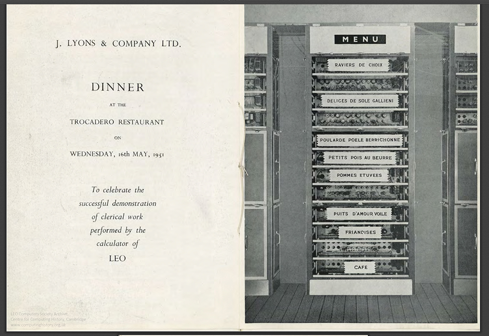
In 1951 LEO staff enjoyed a celebratory dinner at the Trocadero restaurant in London. It was to acknowledge the successful demonstration of clerical work performed by the 'calculator of LEO'.
If you would like to know more about the event, use this link.
Menu for Lyons Dinner at the Trocadero.
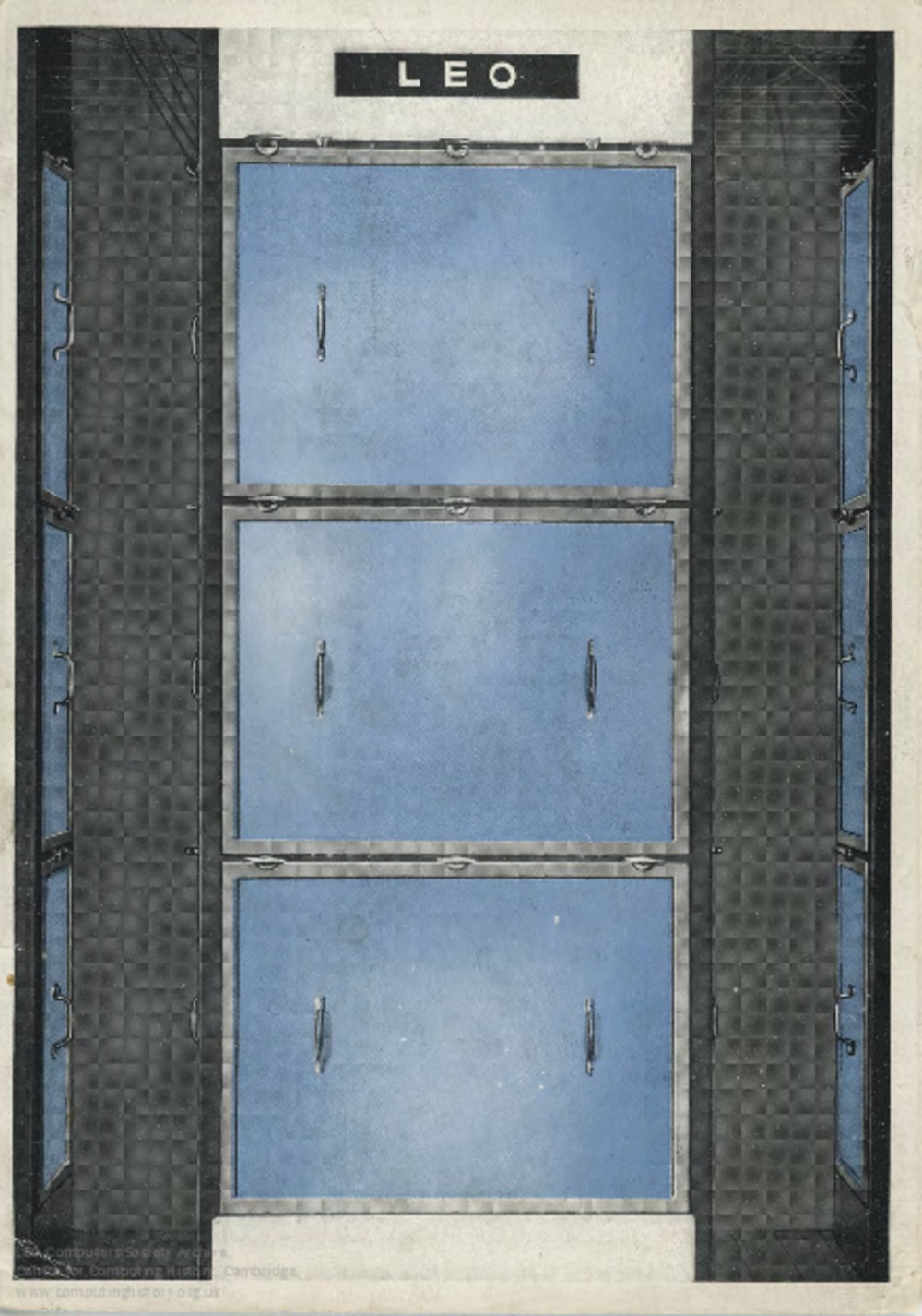
Those attending the event were presented with a menu whose cover included a colourised photograph of one of LEO's racks. On the front of the menu, the rack appears with the panel covers in place and elsewhere, with the covers removed. The question arises, however, which rack was used as the 'prop' for the menu cover?
In our LEO PhotoApp, image number 57 and 13 show the original black and white photographs that were used to mock up the menu covers.
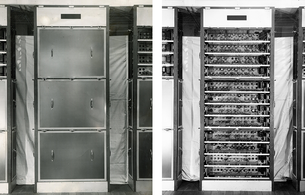
You can see that the menu designers had to perform some creative art to 'tidy' up the photographs and add an approximation to the 'blue' of the LEO panels. All long before the days of Photoshop.
The menu (image 13 in the PhotoApp) shows a rack fully populated with units from the side showing the valves. Now, this presents rather a puzzle. To take a photograph of a rack like image 13, the photographer would have needed a significant distance in front of the rack to ensure that the rack's top and bottom were in view. The only possible row of racks that offered the space needed was the row closest to the centre of the room. However, this row shows its electronic component side to the room's centre and not the valves! So how did they get this photograph and which rack was used?
A few steps back in the timeline might reveal the answer. In the period that represents LEO's construction and early development, LEO had only three rows of racks and not four. You can see that clearly in this image (PhotoApp 8).
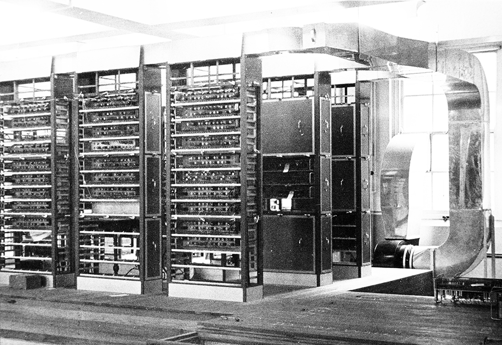
Look closely and you can see that in 1950 the false floor had not been extended yet to accommodate a fourth row of racks. The row exposed to the centre of the room was of course the valve side and would have offered racks that could have been used for our menu photograph.
Exploring photographs in the collection taken about that time, we find PhotoApp 43, the Group photo taken in 1950 with a LEO (of three rows) in the background.
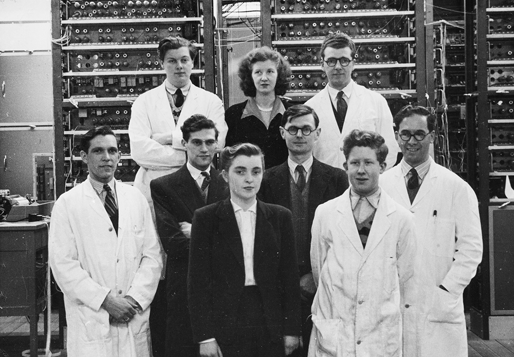
The rack of interest is the one behind Wally Dutton, on the right. With the aid of Photoshop and some patience comparing this part of photo 43 with the menu photo, panels off - PhotoApp 13, you can compare the valve layout, wiring configuration and even some small marks on the racks themselves. There is a very high probability that this is the rack used for the menu photographs.
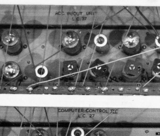
Closer inspection of the rack in PhotoApp 13 shows that the electronic units found in the rack serve several purposes and can be identified by the valve configuration plus some labelling revealed by Photoshop's zoom facility. From the top-down, units 2 and 3 are the Accumulator in/out Unit (LC37) and the Computer Control III (LC27).
Units 6 and 7 are two Mercury Delay Line Store controllers. The valve configuration matches the 'store unit' kept at the Science Museum and shown here.
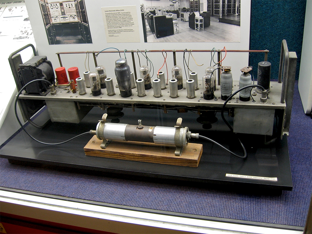
The Science Museum LEO display.
Also at each end of the store units, you can see the two connectors and cables for each unit that will run down the rack (behind), through the floor and off right to the mercury delay lines in the 'vault' under the floor.
The bottom two units appear to be a 'Feeder' and the Outlet Control Unit III (LC62).
The mystery of the menu is therefore solved (I think).
Apart from solving a small mystery, the reason for this research was to identify the rack so that a similarly open rack could be included in the virtual LEO currently under construction. It was important to us to make sure we accurately represented where the rack would appear in the four row LEO being built.
Posted by: Chris Monk
|


